
By Dan and Daren Savage
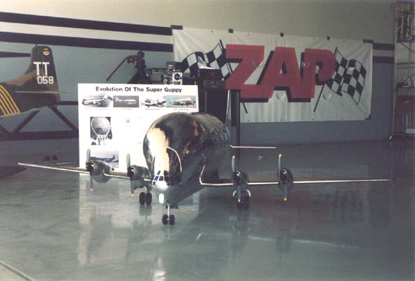
It could probably be said that designing and building a flying model of the Aero Spacelines 377SGT "Super Guppy" represents the worst-case scenario for an electric-powered, multi-engine model. The airplane has a huge fuselage and a tiny wing. The amount of drag generated by the design would seem to be enormous, and the wing loading from a 13-pound model with a 560 sq. in. wing, is frankly, scary. The power-to-weight ratio from electric-powered models doesn't build too much confidence in the final success of the model. In fact, the project was dropped at one time because we felt that maybe the design was a little too far behind the proverbial eight-ball to fly well, or even at all. After more discussion, we decided to go ahead with the project.
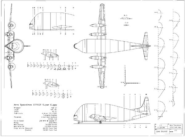
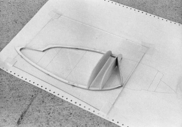
About 90-percent of the model parts, all construction plans, construction and assembly jigs were designed using DesignCAD 3D (DC3) and printed on a Toshiba 1351 dot matrix printer. I started with a 1/144-scale Revel plastic model. Before assembling the plastic kit, I traced the fuselage, inboard and outboard nacelles, wing and horizontal tail outlines on paper.
I made templates using a carpenter's contour gauge of every vertical
panel line on the fuselage and nacelles and traced these into their proper
places on the side view outline of the fuselage. I used these as fuselage
bulkheads and nacelle formers. I made two templates from the wing; one
root and one tip, top and bottom to be used to create all my wing ribs.
Now that I had all the outlines, I was ready to scan them into the computer.
 I scanned the drawings into a PCX format using the Logitech Scanman+ and
a Scan-Align hand-scanner guide.
I scanned the drawings into a PCX format using the Logitech Scanman+ and
a Scan-Align hand-scanner guide.
I highly recommend the use of this or similar guide when using a hand-scanner.
Not only does this take away the "jigglies," but with care I've
scanned drawings that are as good as any flatbed scanner. I converted
the drawings to DXF format using a public domain "H-Line" raster-to-
vector program. Lastly, I converted these to DC3 format using the DXF
program that comes with DC3. Once in DC3, with the scanned image in one
layer, I created a side view outline of the fuselage, then traced the
bulkheads and erected them into 3- dimensional space to form top and bottom
keel and bulkhead outlines in another. 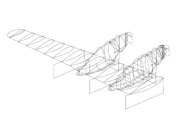
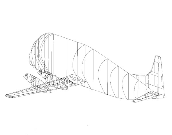
Next, I connected the bulkhead outlines into a 3-D surface using the "Connect-Smooth" and "Connect" commands. This gave me a surface to render using the "Shade" command and to verify the outlines for accuracy and fit. I used the same procedure for the inboard and outboard nacelles, which of course, are different from each other. I used a different command to create the wing ribs. After tracing the wing leading and trailing edges, I put the root and tip rib outlines into their respective places on the wing planform. I created a surface using the "Patch" command. This command asks for two parameters that are perfect for creating wing ribs. These are vertical and horizontal number of breaks. Translated they work out to be chord-wise resolution of the rib outline, and the number of ribs to put between the root and tip rib.
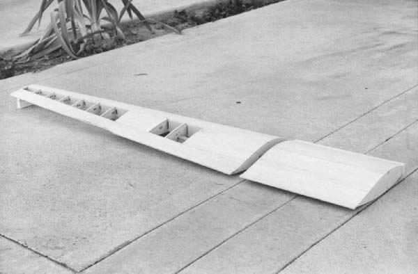
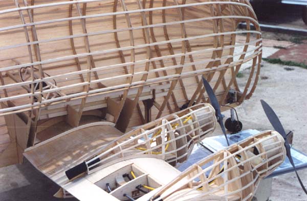
The design my brother Daren and I had in mind was to be electric-powered for simplicity, reliability and lightness. After lengthy discussion we decided that the lightest construction method we could think of was semi-monocoque: the old Guillow method. In the end, we put down top and bottom keels over the plans, glued the bulkheads in place, put the side keels in, then put the stringers in. We decided to use open-bay construction on the nacelles, but couldn't decide whether to sheet the fuselage or leave that open-bay for lightness. DC3 to the rescue!
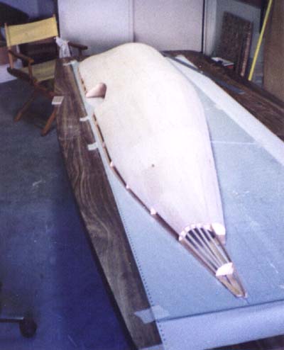
I did a surface-area calculation on the fuselage skin created earlier, and found out that the surface area of the Guppy was 23 square feet. I calculated the weight of 1/32-inch contest and discovered that the sheeting would only add 6- 8 oz. to the fuselage. The wing used D-Tube construction and the tail feathers were built-ups. Because the bulkheads were so big, and the keels so long, we used 3'x7' mahogany plywood door skins for all the plywood parts in the model. The construction of the Guppy presented a number of technical problems that had to be overcome to produce a successful model like this.
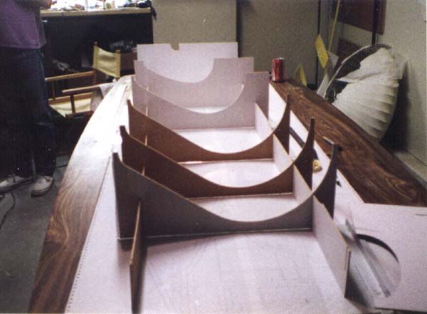
 The typical Guillow fuselage is built by pinning the top and bottom keel
to the building board, over the plans. Gluing the bulkheads to the keels,
and gluing in the side keels and stringers. Well, up to this point, the
Guppy was built the same way, except that we also added 1/32" balsa
sheeting afterward. After you popped the fuse off the board, you built
the other side of the fuselage in your lap. You don't build a 7-foot fuselage
in your lap! Or on the building board, at least, not without jigs.
The typical Guillow fuselage is built by pinning the top and bottom keel
to the building board, over the plans. Gluing the bulkheads to the keels,
and gluing in the side keels and stringers. Well, up to this point, the
Guppy was built the same way, except that we also added 1/32" balsa
sheeting afterward. After you popped the fuse off the board, you built
the other side of the fuselage in your lap. You don't build a 7-foot fuselage
in your lap! Or on the building board, at least, not without jigs.
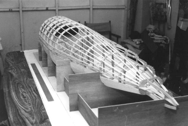
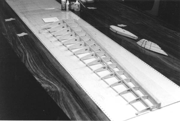
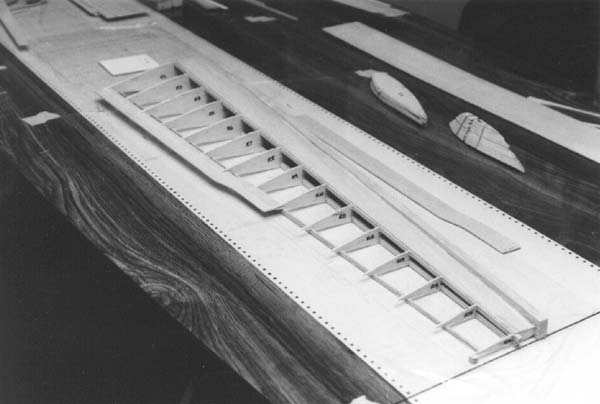
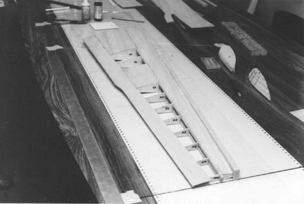
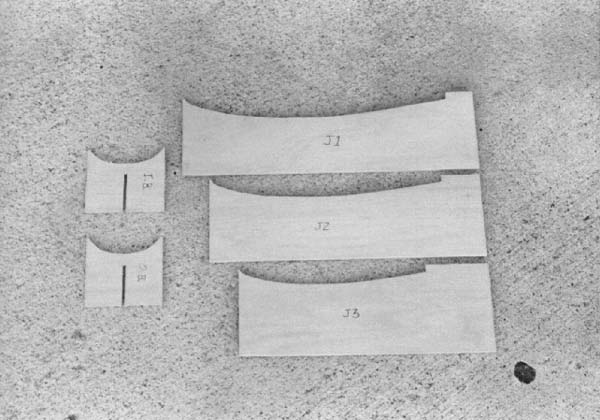
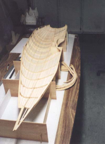 Working in DC3, I erected the bulkhead outlines into 3-dimensional space
creating a 3-D model of the fuselage in this stage of construction. I
rotated this fuse 90 degrees on the "roll" axis of the model,
so the open side was up, and added new lines from the top and bottom of
each bulkhead, down to an imaginary "floor." I drew a line was
connecting these two lines to each other to form a 3-sided rectangle.
This and the bulkhead outline were combined to create a single entity
which could be rotated and moved around to create the fuse jig pieces.
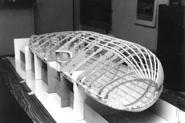
It uses eggcrate construction to form a cradle that supports the fuselage
and keeps it square, so the other side may be built, producing a straight
and extremely light, strong fuselage. The bare fuselage, covered, without
hardware weighed 2 pounds.
Working in DC3, I erected the bulkhead outlines into 3-dimensional space
creating a 3-D model of the fuselage in this stage of construction. I
rotated this fuse 90 degrees on the "roll" axis of the model,
so the open side was up, and added new lines from the top and bottom of
each bulkhead, down to an imaginary "floor." I drew a line was
connecting these two lines to each other to form a 3-sided rectangle.
This and the bulkhead outline were combined to create a single entity
which could be rotated and moved around to create the fuse jig pieces.
It uses eggcrate construction to form a cradle that supports the fuselage
and keeps it square, so the other side may be built, producing a straight
and extremely light, strong fuselage. The bare fuselage, covered, without
hardware weighed 2 pounds.
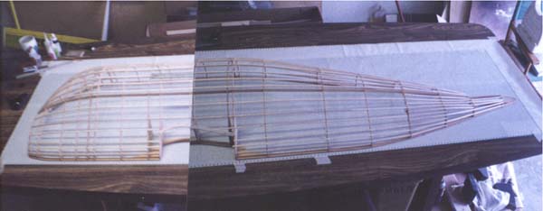
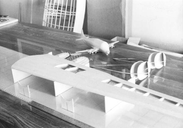
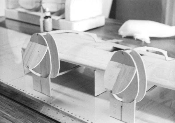
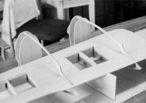
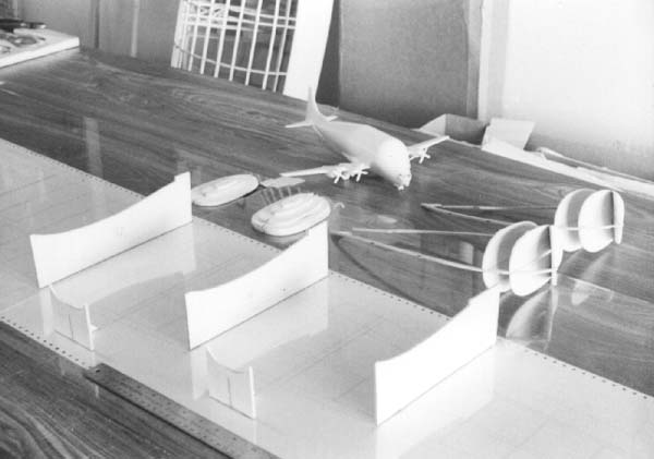
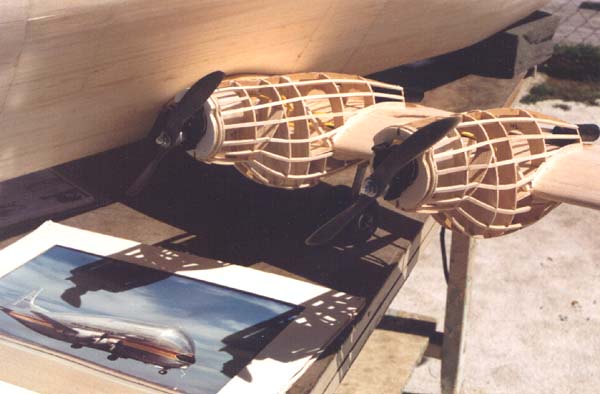
The wing itself, was very conventional construction. It has standard D-tube exactly like any Great Planes Super Sportster, balsa spars, and all. The nacelles, on the other hand had to be aligned accurately if the Guppy was to fly. To overcome this obstacle, I built a 3-dimensional CAD line model using all the outlines of the wing and the inboard and outboard nacelles. The wing's incidence was set to positive 2 degrees to an imaginary "floor" and the 3-D nacelles were put into proper place on the wing using the bottom of the nacelle where it meets the trailing edge of the wing.
The nacelles were set with the firewall set to zero-zero. Using the same method as the fuse, lines were drawn from the nacelle formers and wing ribs to the imaginary "floor," connected and combined to create the jig pieces to hold the wing in at 2 degrees incidence and the front of the nacelles in their proper location in relation to the wing for assembly. Were the jigs worth the trouble to design and construct? They sure were, and they would allow anyone to build a flying model of the Guppy.
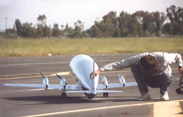
 Since neither of us had built an electric-powered model before, much less
a multi-engine electric model, we decided to build a test stand that would
measure rpm, amp draw, voltage, and static thrust. The design that emerged
was made from pieces of scrap lumber, an old aluminum landing gear and
nose gear assembly from a model long gone. We bought the 30-amp amp-meter
and 50- volt voltage meter from a local electronics house for eight dollars
each, and used an accurate spring scale to measure thrust.
Since neither of us had built an electric-powered model before, much less
a multi-engine electric model, we decided to build a test stand that would
measure rpm, amp draw, voltage, and static thrust. The design that emerged
was made from pieces of scrap lumber, an old aluminum landing gear and
nose gear assembly from a model long gone. We bought the 30-amp amp-meter
and 50- volt voltage meter from a local electronics house for eight dollars
each, and used an accurate spring scale to measure thrust.
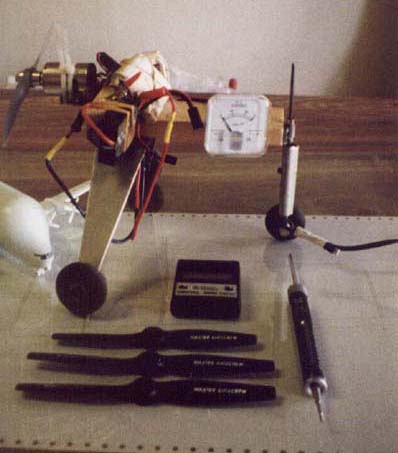
The test rig was set up to run one motor using a 7-cell, 1700mAh battery back and we used the speed controller that was to be used in the model. When we were in the early stages of design, we intended to run the motors direct drive to use 8-inch propellers, which are the scale size, and we wanted to use ferrite motors for economy. We used the commonly accepted formulas to calculate power loading in watts per pound. We calculated the weight of the power system including motors, batteries, speed controller, wiring and connectors. These weighed 5 and 1/2 pounds. The accepted method says the finished, ready to fly airplane should weigh no more than twice the weight of the power system. So we had 11 pounds as the flying weight. Current thinking says we should be pumping at least 650 watts through the motors to safely fly our model.
When we set up our test rig with a Great Planes Goldfire 05 motor, installed an APC 8x4 prop, and ran it, the thrust wasn't nearly what we had hoped. We were producing less than a pound of thrust. Four pounds of thrust wouldn't be nearly enough to fly a model of this size and weight. We've both been flying R/C models long enough to know this much. Let's try a different prop, we thought. We tried almost every sport APC prop between 8x3 and 10x6 and even two APC 8x8 and two Zinger 8x4 props bolted on top of each other to try a couple of four-bladed configurations. We even threw on a wood 14x6 just for fun. No prop would produce more than a pound of thrust. We grabbed the prop that produced the highest thrust, an APC 8x5, the test rig, and headed down to the hobby store to test some motors. We tried a hotter motor, then another and another. No matter how many amps we pumped through the motor, we couldn't get the test rig to produce more that one pound of thrust. We needed to think about this one.
While reading a model magazine, we saw an ad for Model Electronic's claim for remarkably high thrust levels they were achieving from 05 ferrite motors, so we gave them a call. We spoke with the owner, Roland "Pete" Peterson, a very courteous and helpful gentleman, who recommended his Sport Combat motor/gearbox combination for the Guppy. He said he was getting 31 ounces of thrust using 7-cell battery packs and a 10x6 prop. We ordered a unit for testing. When the motor arrived, we put it through the paces on the test rig and two setups emerged and the ones that held the most promise.
The first and simplest, was an APC 10x6, producing 1.67 pounds of thrust turning 7000 rpm and drawing 19 amps of power. The second was two stacked APC 8x8's, producing 1.51 pounds of thrust turning at 6800 rpm and also drew only 19 amps of power. We were producing more thrust and using less power. Now we felt comfortable with the thrust to weight ratio. We came to the conclusion that thrust to weight ratio was a far more important figure than watts per pound.
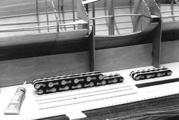
The motors were wired in series, as were the batteries. These were connected in a conventional manner to a 28-cell high-frequency, high voltage electronic speed controller. The motors are run through 3.8:1-ratio gearboxes and were synchronized on the bench by adjusting the timing on the motors at idle. The four motors were never more than 100-200 rpm out of sync with each other. The props turned right around 7000 rpm and provided between 1.5 and 2 pounds of thrust each, for a total of between 6 and 8 pounds of thrust.
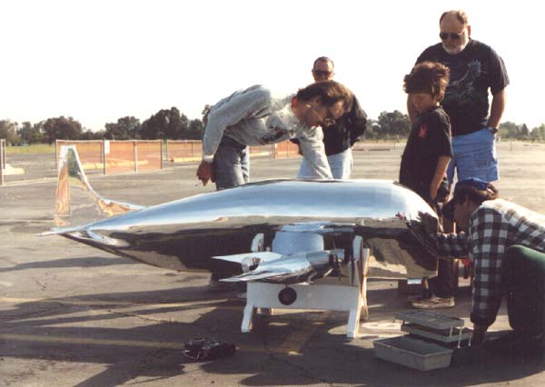
Before a Guppy will fly, it's center of gravity must be determined, and the model balanced. How do you find the C.G. on a model like this? In DC3, I took the wing planform, including tip, and combined it into a single entity, and used the "Center-Of-Gravity" command. This gives the geographic center of the mass, which in the case of a 2-D wing planform corresponds to the mean aerodynamic chord of the wing. I calculated 28-percent of the distance from the leading edge to the trailing edge of the wing at that point, and moved to the root rib and measured from the leading edge to this point. So far, so good, it looked right for the shape of the wing, but on the first test flight, the model was wildly tail-heavy and crashed.
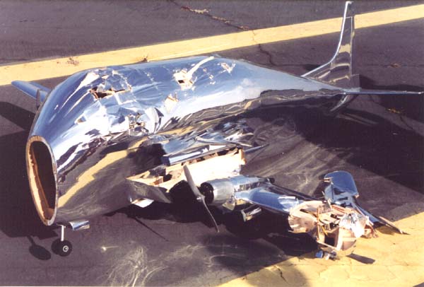
The left wing was broken off at the number one nacelle, which was also destroyed and the fuselage was crushed and broken in three places. The model was repaired, but what about the C.G.? We originally had the main landing gear wires bent to the scale angle, about 10 degrees forward of straight down. With the C.G. at the calculated location, the model wouldn't sit on it's nose gear, so we angled the main wires back enough so the model would sit comfortably on the ground. We later said that this should have been our first clue. What wasn't calculated into the equation was the lift coming from the fuselage. Not only was the fuselage providing lift, but it's center of lift was much further forward than the wing's. The more we sat around, discussing how to calculate the C.G. for a shape like the fuselage, the worse our heads hurt.
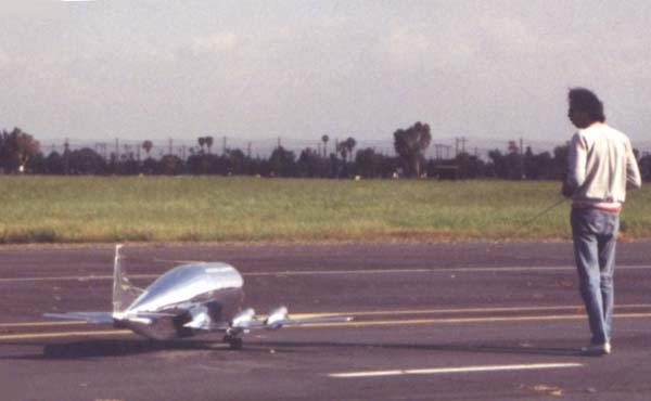
We finally decided to simply re-bend the main gear wires to their original and scale angles and balance the airplane so the C.G. was 1 and 1/2 inches ahead of the main gear axle. Second test flight, and success! It flew, and in a very scale-like manner. We maintained that since we used 100-percent scale outlines on the model, including airfoil, and since the original flies with the mains set to that angle, so should the model, and it did.

The airplane flew surprising well considering it's size, shape and weight. It was very stable on the ground and in the air, though it did like to have rudder held in during turns. Electric-powered models are known for their high weight and low thrust levels. You reap an additional benefit when you run more than one prop on an airplane, and that's one of the reasons the Guppy flew.
We saved a lot of weight in the wing and nacelles. This pays off with a slow and lumbering flight profile. The electrics sound just like turboprops. The sound produced by these combined with a slow flight speed produce a very slow Doppler shift, making the Guppy very realistic in the air. All in all, we were very pleased with our results.
It took me one and a half years to complete the design working on the computer between other building projects and flying sessions.The construction took about 6 months from the first piece of wood being cut to the first test-crash, and another 2 months to repair and test fly again. We didn't apply the finishing touches because we weren't sure if the model would fly at all, much less if it would fly very well, so that's why we only finished it enough to make it airworthy and then let it prove itself.
It was, for us at least, a flying test-bed that represented a few firsts for us: it's our first giant-scale, first electric, first multi-engine model and my first scale design using the computer as the primary design tool. I've become so hooked on using CAD, that every drawing I create anymore is done in CAD. It's the only drafting table I use. The Toshiba printer is a 24-pin, wide carriage printer that can handle 14-wide continuous-form paper and prints graphics at 180 dots-per-inch, which translates into 1/180 of an inch resolution. Plenty accurate for model airplanes and reproduces small details very well. We learned a lot from this project, and now have the tools to design and build a scale model from just about any plastic model on the market.
Here are the model's specifications: Length: 83", Wingspan: 88", "Actual" Wing Area: 560 Sq. In., Weight: 13 Lbs., Wing Loading: 53 Oz./Sq. Ft.- (Yikes!), Overall Height: 29", Power: 4 - Model Electronics Sport Combat motors using Leisure 3.8:1 gearboxes, Propellers: APC 10-6, Power Pack: 28 1700 mAh Sub-C Cells, Estimated Top Speed: 50 mph, Estimated Cruise Speed: 35-40 mph, Estimated Stall Speed: 15-20 mph, Radio Channels Used: 4 (Aileron, Elevator, Rudder & Throttle).
Movies
 This
video was shot of the Guppy's first successful test flight. Dan won the
coin toss for the first test flight which resulted in the crash(through
no fault of his own), so now it was my turn to try my hand at the helm.
I let the Guppy build up speed on the take off roll... it lifted off by
itself and began a gentle climb-out, with only minor trim adjustments, flying
as if that's what it wanted to do all along. This solved the problem we
had with limited rotation angle. It's a probably a good thing the Guppy
flew as well as it did, because I was pretty nervous. The Free Flight guys
flying across the hobby area of Mile Square Park certainly got quite a show
that day.
This
video was shot of the Guppy's first successful test flight. Dan won the
coin toss for the first test flight which resulted in the crash(through
no fault of his own), so now it was my turn to try my hand at the helm.
I let the Guppy build up speed on the take off roll... it lifted off by
itself and began a gentle climb-out, with only minor trim adjustments, flying
as if that's what it wanted to do all along. This solved the problem we
had with limited rotation angle. It's a probably a good thing the Guppy
flew as well as it did, because I was pretty nervous. The Free Flight guys
flying across the hobby area of Mile Square Park certainly got quite a show
that day.(1655K QuickTime video)
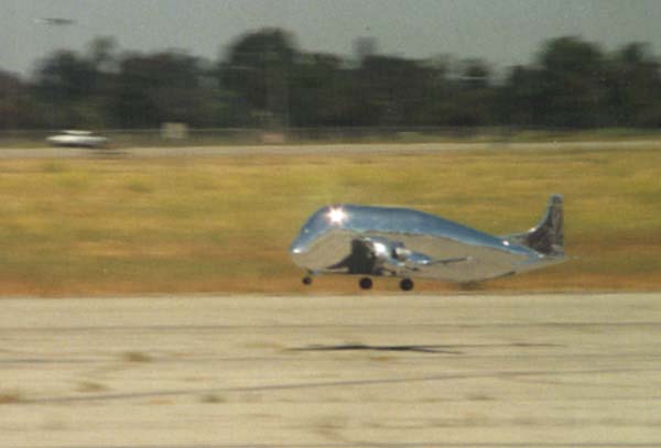
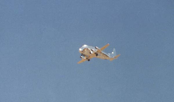
 The
Guppy is seen during an overhead flyby. The sound of the geared electric
motors, combined with the slow speed at which the airplane flew, was better
than we could have hoped. The motors held their sync, never missing a beat.
There was some question in our minds before this flight, regarding the small
size of the control surfaces and how efective they would be. It turned out
to be not a problem at all. The control in all axis was good without being
overly sensitive (Right!).
The
Guppy is seen during an overhead flyby. The sound of the geared electric
motors, combined with the slow speed at which the airplane flew, was better
than we could have hoped. The motors held their sync, never missing a beat.
There was some question in our minds before this flight, regarding the small
size of the control surfaces and how efective they would be. It turned out
to be not a problem at all. The control in all axis was good without being
overly sensitive (Right!). The Guppy took longer to build than we had anticipated, was more work than had been planned, caused much too many headaches, and reaped for both of us, more rewards personally, than all of the problems combined. The Guppy steals even the best Mustang's thunder.
(1354K QuickTime video)
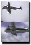 There is an issue running through the scale Radio Control (R/C) modeling
community right now regarding what is the correct scale speed. We believed
while flying our R/C Guppy especially after viewing video footage performed
in a very scale like fashion. This was due to many factors such as wing
loading, power loading, sound and doppler effect.
There is an issue running through the scale Radio Control (R/C) modeling
community right now regarding what is the correct scale speed. We believed
while flying our R/C Guppy especially after viewing video footage performed
in a very scale like fashion. This was due to many factors such as wing
loading, power loading, sound and doppler effect. After reviewing the recent footage we shot of NASA 941's take off from Los Al we decided to put it to the test by creating a video which shows the two Guppys, the model and the full size flying side by side. What you see here is the result of those efforts. Some of the differences seen are a result of the scale distances being different; i.e. either the model is too far away or the full size is too close.
Comments or Questions? Email me
Copyright © 2006 Daren Savage
All Rights Reserved