 The accident occurred during the sixth takeoff of Flight Number
12 following the scheduled cut of the number one engine at an indicated
airspeed of about 109 knots. The takeoff was being made on Runway Number
22 and the wind was from approximately 200 degrees at about 10 knots.
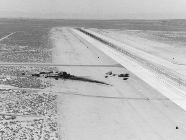
The accident occurred during the sixth takeoff of Flight Number
12 following the scheduled cut of the number one engine at an indicated
airspeed of about 109 knots. The takeoff was being made on Runway Number
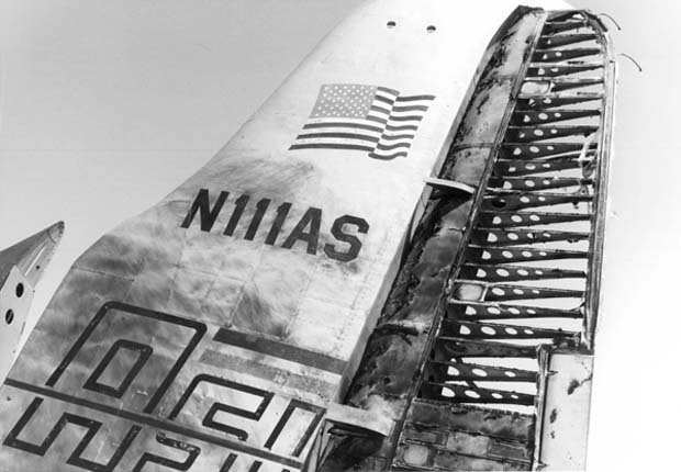
22 and the wind was from approximately 200 degrees at about 10 knots. Rotation occured at about 114 knots and several seconds after rotation, according to one witness, the aircraft turned and rolled to the left, settling as it did so. The left wingtip subsequently contacted the ground which resulted in the aircraft being forcibly yawed from an initial magnetic heading of about 245 degrees, according to the flight data recorder, to a final heading measured as about 020 degrees. As a result of this cartwheeling action, the forward section ot the aircraft was rammed into the ground and was demolished, killing the four crewmembers.
(35K JPG image)
 Lost in the accident was Pilot Van Shepard (ASI VP), Co-Pilot
Hal Hansen (ASI Chief Pilot), Flight Engineer Travis Hodges and Flight Test
Engineer Warren (Sam) Walker. The takeoff roll and scheduled engine cut
were apparently routinely accomplished. The engine cut was scheduled to
be made at a calibrated air speed of 112 knots, but was actually cut at
about 108 knots at about 3 seconds preceding rotation.
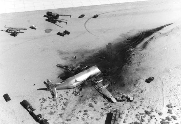
Lost in the accident was Pilot Van Shepard (ASI VP), Co-Pilot
Hal Hansen (ASI Chief Pilot), Flight Engineer Travis Hodges and Flight Test
Engineer Warren (Sam) Walker. The takeoff roll and scheduled engine cut
were apparently routinely accomplished. The engine cut was scheduled to
be made at a calibrated air speed of 112 knots, but was actually cut at
about 108 knots at about 3 seconds preceding rotation. The test was to be conducted with the rudder boost on and according to data gathered from the flight data recorder, the right rudder pedal force utilized throughout the latter portion of the takeoff roll, as well as just following rotation, appeared normal and apparently effected the desired or required right rudder position.
One second after rotation there was a rapid reversal in rudder direction from right to left followed by an apparent divergence in directional sense between rudder pedal force and rudder position actually commanded, i.e., an increasing pedal force to the left is associated with an increasing right rudder position.
(40K JPG image)
 A check of available parts of the engines and propellers did not
find any abnormal operations of either the propellers or engines. The propeller
blade shims were checked at the accident site by a representive from Hamilton
Standard, manufacturers of the propellers. The propeller blade shims indicates
the No.1 propeller was in a feathered position and Nos.2,3 and 4 were in
normal operating positions.
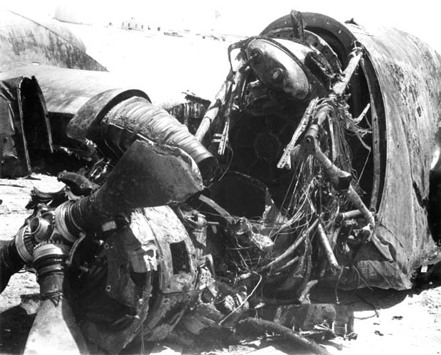
A check of available parts of the engines and propellers did not
find any abnormal operations of either the propellers or engines. The propeller
blade shims were checked at the accident site by a representive from Hamilton
Standard, manufacturers of the propellers. The propeller blade shims indicates
the No.1 propeller was in a feathered position and Nos.2,3 and 4 were in
normal operating positions. The engines were taken to the Aero Spacelines' facilities at Santa Barbara Airport for disassembly and inspection. This inspection showed that the FOD damage found was caused at the time of impact and there was still some sand in the compressor section. There was some build up of aluminum on the thermocouples of Nos. 2, 3 and 4 engines, which is normal since the engines were operating at normal temperatures at the time of impact causing the blades to rub the case, throwing aluminum to the rear of the engines. Since the thermocouples were hot, the aluminum melted and stuck to them. The No.1 engine was shut down, therefore, the thermocouples were cool and the aluminum did not adhere to them. It was determined that the engines were operating normally at the time of impact.
(66K JPG image)
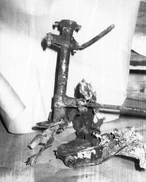
 Examination of the Rudder System revealed the the Rudder Bell Crank Arm
Assembly, Boeing P/N 15-23765 and the Rudder Boost Control Link Assembly,
Boeing P/N 6-38900 were broken. The broken assemblies were removed and forwarded
to the NTSB Metallurgist for fracture analysis. The fractures were typical
of bending overload breaks.
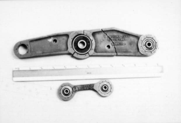
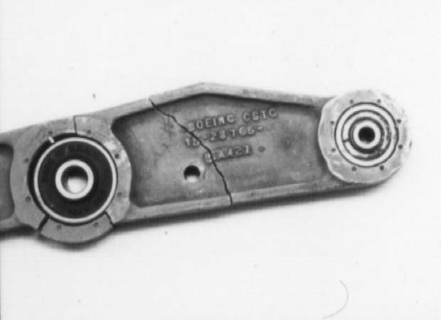
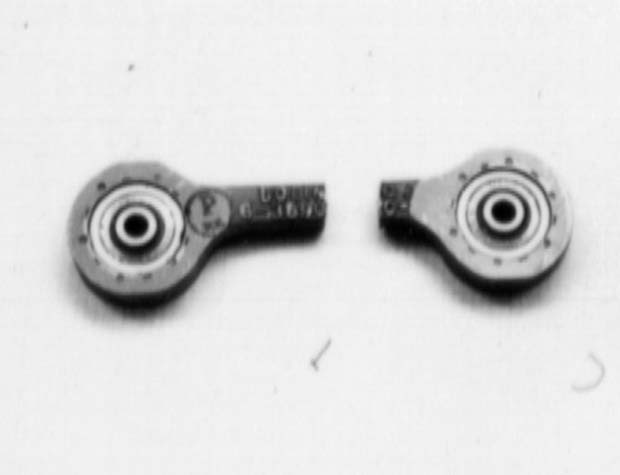
Examination of the Rudder System revealed the the Rudder Bell Crank Arm
Assembly, Boeing P/N 15-23765 and the Rudder Boost Control Link Assembly,
Boeing P/N 6-38900 were broken. The broken assemblies were removed and forwarded
to the NTSB Metallurgist for fracture analysis. The fractures were typical
of bending overload breaks. A functional test of some of the Rudder Boost Package components after its removal, was performed at Hydro-Aire, Burbank, California. Under the direction of a Boeing expert hired under a contract with Boeing, an overall system check was performed at ASI in Santa Barbara, California. Upon completion of the functional testing, disassembly inspection of all components of the package was performed. There was nothing of significance found.
(17K JPG image)
 The rudder cable system suffered severe impact and fire damage. The right
rudder cable quick-disconnect was found unlatched and disconnected. Examination
of all other cable disconnects revealed them to be latched and safety-wired.
It could not be determined if the right rudder quick-disconnect was safety-wired
prior to the accident, however it was the only latch found disconnected
in the aircraft's quick-disconnect cable system.
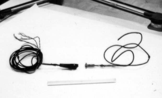
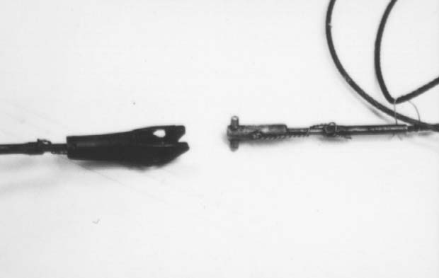
The rudder cable system suffered severe impact and fire damage. The right
rudder cable quick-disconnect was found unlatched and disconnected. Examination
of all other cable disconnects revealed them to be latched and safety-wired.
It could not be determined if the right rudder quick-disconnect was safety-wired
prior to the accident, however it was the only latch found disconnected
in the aircraft's quick-disconnect cable system. The latch mechanism was forwarded to the NTSB for determination of safety wire installation prior to impact. It was noted that the latch handle portion of the disconnect assembly was subjected to severe heat and fire damage, but that the attaching clevis portion of the assembly was not.
(18K JPG image)
 The pilot's rudder pedal assembly was not recovered. Only the
co-pilot's rudder pedal assembly was recovered and its rudder pedal adjustment
levers were found to be intact. Reviewing the maintenance records and pilot
remarks noted in the aircraft logbook, there were several remarks written
up regarding erratic rudder operation.
The pilot's rudder pedal assembly was not recovered. Only the
co-pilot's rudder pedal assembly was recovered and its rudder pedal adjustment
levers were found to be intact. Reviewing the maintenance records and pilot
remarks noted in the aircraft logbook, there were several remarks written
up regarding erratic rudder operation. On March 18, 1970, prior to test flight No.2, the crew reported that the rudder moved sharply when the Gust Lock was released and hit the rudder stop hard. The crew was unable to activate the rudder boost system and elected to take off with the system inoperative. One quarter rudder was observed and the rudder could not be centered.
As the aircraft reached approximately 50 knots, an increased scrub of the nosewheel was felt by the pilots as increased right steering was needed as speed increased to counteract an apparent locked rudder. The takeoff was aborted when the aircraft left the centerline of the runway. High right rudder force would not move the rudder pedal. Inspection of the entire rudder system did not reveal any discrepancy; however, the inoperative rudder boost system was corrected by adjusting the Gust Lock switch and the cable system quick-disconnect latches were taped over to prevent possible interference with adjacent latches.
(14K JPG image)
 On March 19, 1970, No.3 test flight the pilot reported directional
control problems on a Post Summary Status Report Sheet and the Pilot Discrepancy
Sheet. He remarked that "No.1 engine reduced to flight idle at V1. No problems
encountered with VMCG; however, difficulty was encountered in maintaining
directional control in flight at 121 knots. Trouble could have been in that
the wing was allowed to drop excessively in the initial climb".
On March 19, 1970, No.3 test flight the pilot reported directional
control problems on a Post Summary Status Report Sheet and the Pilot Discrepancy
Sheet. He remarked that "No.1 engine reduced to flight idle at V1. No problems
encountered with VMCG; however, difficulty was encountered in maintaining
directional control in flight at 121 knots. Trouble could have been in that
the wing was allowed to drop excessively in the initial climb". On March 20, 1970, No.4 test flight, the pilot remarked that at 120 knots the amount of rudder available varied from 9 to 21 degrees with rudder boost on and full rudder pedal. The corrective action written up was "bled excessive air from system, operation checks OK".
On a Pilot Summary Status Report Sheet dated March 25, 1970, it was noted that "No.1 engine to flight idle at V1, and no difficulty was encountered because of varying rudder position with full pedal. Shortly after takeoff, it was found that rudder control was normal with boost off. 20 to 23 degrees was available with approximately 200 lbs. of force. However, generally only 9 to 10 degrees of rudder deflection was available the majority of the time. With constant full pedal, rudder position was erratic above 10 degrees part of the time".
(18K JPG image)
 The recovery of the Photo Instrument Panel film made it possible
to obtain complete data of the last flight of N111AS. This data included
No.1 engine RPM, angle of attack, "g" load factor, side slip in degrees,
elevator stick forces and elevator deflection, rudder position and forces,
airspeed and aileron position. Two seperate tests were performed in an attempt
to duplicate the traces of this data using the 377SGT N211AS nearing completion
at ASI in Santa Barbara, California.
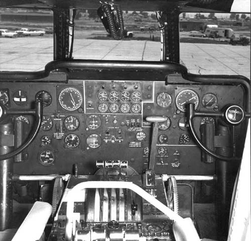
The recovery of the Photo Instrument Panel film made it possible
to obtain complete data of the last flight of N111AS. This data included
No.1 engine RPM, angle of attack, "g" load factor, side slip in degrees,
elevator stick forces and elevator deflection, rudder position and forces,
airspeed and aileron position. Two seperate tests were performed in an attempt
to duplicate the traces of this data using the 377SGT N211AS nearing completion
at ASI in Santa Barbara, California. The first test was done on June 3, 1970. As no hydraulic power was available, the tests were made with the Rudder Boost System inoperative. Consequently, these tests were inconclusive. Test No.2 was performed on July 1, 1970 using the same aircraft. This test was made with the Rudder Boost System operating and produced traces with some simularity to the accident traces.
(11K JPG image)
 This graph is a cross plot of rudder pedal force and rudder angle
for flight 23, takeoff number 6, from counter number 8799 through time of
impact. The dashed line represents the force vs. position relationship as
defined by special calibration on May 7, 1970. The line is a bit misleading
because it does not fully show the wide hysteresis band that exists with
rudder boost on. In studying the data time histories and this cross plot,
test engineers at ASI considered many possibilities such as cable binding,
quick disconnect release, hydraulic problems, rudder boost system failures,
etc.
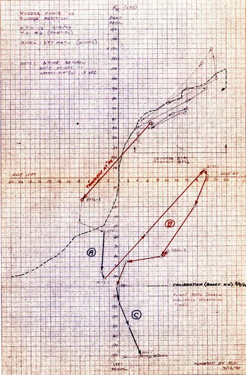
This graph is a cross plot of rudder pedal force and rudder angle
for flight 23, takeoff number 6, from counter number 8799 through time of
impact. The dashed line represents the force vs. position relationship as
defined by special calibration on May 7, 1970. The line is a bit misleading
because it does not fully show the wide hysteresis band that exists with
rudder boost on. In studying the data time histories and this cross plot,
test engineers at ASI considered many possibilities such as cable binding,
quick disconnect release, hydraulic problems, rudder boost system failures,
etc. After considering all possibilities it was concluded that the portions of the large plot marked "A" and "C" are periods during which the pilot's rudder pedals were jammed in a near-neutral position and the copilot was applying right pedal inputs. The section marked "B" appears to be a temporary release of the jammed condition with both pilot and copilot applying right rudder and then backing off. At counter 8801 the pedals get back to the position at which the jam occurred before. They then appear to bind again and remain that way until impact.
(109K JPG image)
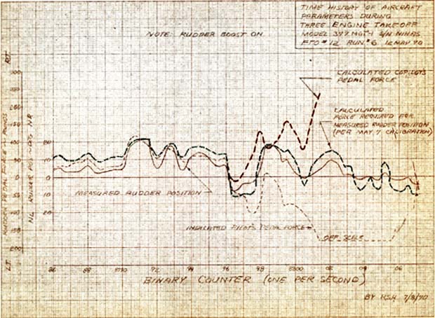 This graph is the time history of rudder position and pedal force
for takeoff number 6. Superimposed on the flight test data are two additional
calculated time histories. The green dashed line is the pedal force required
to produce the measured rudder deflections assuming operation per the May
7 calibrations of force vs. position. The red dashed line is the calculated
copilot's rudder pedal force input which, when added to the indicated force
will yield the required force for measured rudder deflection. The calculated
copilot rudder pedal forces are logical and consistent with the concept
of a binding or jam in the pilot's pedals. ASI test engineers concluded
that other types of failures did not fit the data.
This graph is the time history of rudder position and pedal force
for takeoff number 6. Superimposed on the flight test data are two additional
calculated time histories. The green dashed line is the pedal force required
to produce the measured rudder deflections assuming operation per the May
7 calibrations of force vs. position. The red dashed line is the calculated
copilot's rudder pedal force input which, when added to the indicated force
will yield the required force for measured rudder deflection. The calculated
copilot rudder pedal forces are logical and consistent with the concept
of a binding or jam in the pilot's pedals. ASI test engineers concluded
that other types of failures did not fit the data. An unlatched cable disconnect would have precluded the possibility of any further rudder movement; yet some rudder movement continued up to counter 8803. Cable binding, hydraulic problems, rudder boost system failures, etc. would not have generated the left force indications. Of the many tests and analyses performed, only a binding of the pilot's pedals and copilot right rudder inputs were able to produce the left force indications. This is what was reported to the NTSB. The actual cause of the accident remains undetermined.
(77K JPG image)
Comments or Questions? Email me
Copyright © 2006 Daren Savage
All Rights Reserved